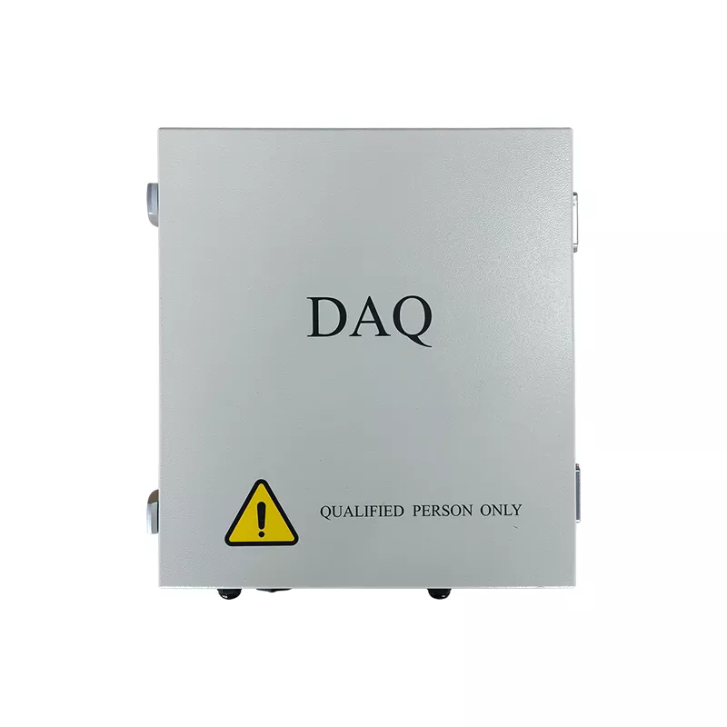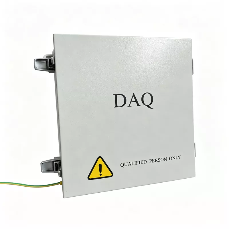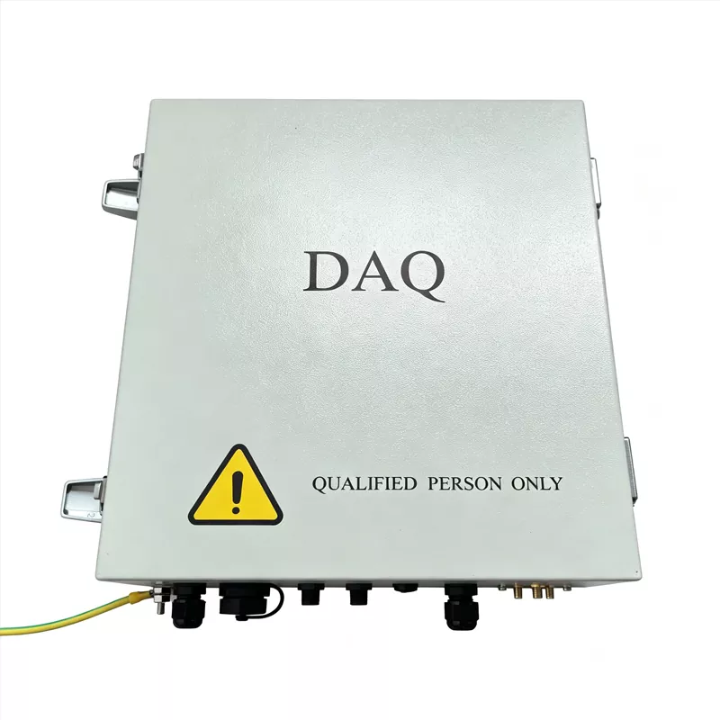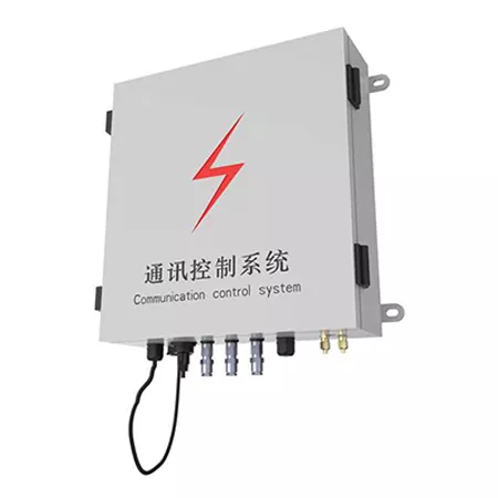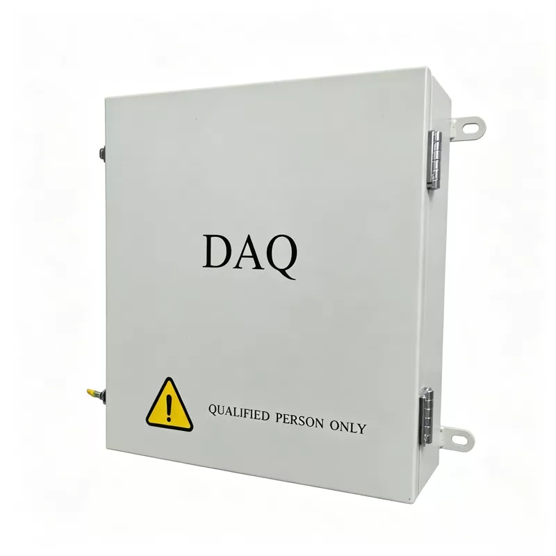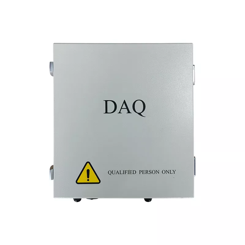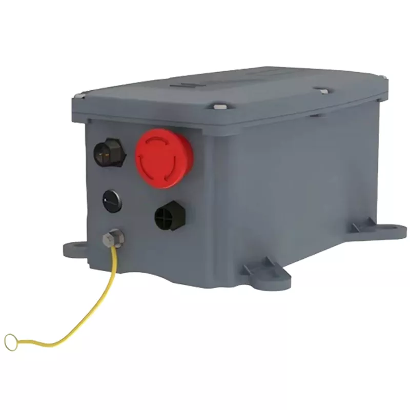

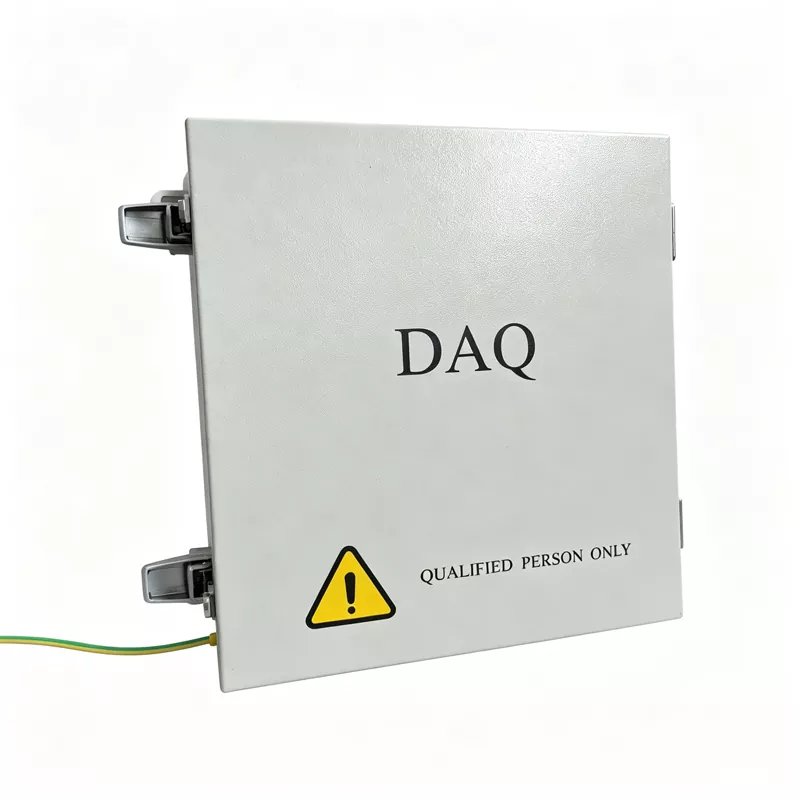
Photovoltaic Communication Unit
Reliable communication is essential for the stable operation of solar power plants in demanding outdoor environments. Choose Ruitai as your supplier, our Photovoltaic Communication Unit provides coordinated device-edge-cloud management, along with strong interference resistance and fault-response capabilities through its optimized system architecture. It supports the 24/7 uninterrupted operation of large-scale solar power plants.
Ruitai is a reliable manufacturer of Photovoltaic Communication Units that integrate device-side data collection, edge-side processing, and cloud-based dispatching.
At the device level, industrial-grade protocol conversion connects legacy equipment with IP networks, helping eliminate data silos. At the edge level, local data caching and intelligent filtering reduce network transmission pressure.
In the cloud, centralized data collection and intelligent analysis support a solar power plant that is visible, reliable, manageable, and controllable.
Product Architecture
1. Dual Power Supply and Backup Power
The Photovoltaic Communication Unit supports both AC and DC power supplies and includes a backup lithium battery.
If AC power is interrupted, it maintains core communication and control functions to help prevent data loss and command interruptions.
2. Industrial-Grade Protection and Isolation
Industrial-grade chips, isolated circuits, and an IP65 enclosure help protect against electromagnetic interference, condensation, and extreme temperatures, reducing the risk of communication module failure or damage in harsh environments.
3. Secure Encrypted Communication
Hardware and software encryption, together with high- and low-voltage isolation, help protect control commands from tampering or interception and support secure remote control of the solar power plant.
Full Specifications Table
▷ Characteristic parameters
|
Product Model |
RT-COM-V1 |
High Wind Speed Trigger Threshold |
Adjustable |
|
Power Supply |
L+N 220VAC |
Heavy Snow Trigger Threshold |
Adjustable |
|
Parameter Setting |
PC |
Latitude and Longitude |
Automatically Obtained by GPS |
|
Daily Power Consumption |
≤0.1kWh |
Time Zone |
Self-Setting |
|
GPS Signal |
Yes |
||
▷ Functional parameters
|
Weather Sensor Alarm |
Yes |
Wireless Communication (with TCU) |
Yes |
|
Communication Interruption Alarm (with TCU) |
Yes |
Communication Port |
RS485 / Ethernet |
|
GPS Module Fault Alarm |
Yes |
Wind Speed |
Yes |
▷ General parameters
|
Housing Material |
Sheet Metal |
Size |
330*96*360mm |
|
Installation Method |
Clamping |
Operating Temperature |
-40~70℃ |
|
Waterproof Rating |
IP65 |
Altitude |
< 4000m |
|
Weight |
5.4kg |
||
Standardized NCU Troubleshooting and Preventive Maintenance
To support the long-term stable operation of the Ruitai Photovoltaic Communication Unit, we provide a standardized troubleshooting and preventive maintenance system to help O&M personnel identify and resolve issues quickly.
Phase 1: Initial On-Site Inspection (Visual, Smell, and Measurement Checks)
Visual and Status Inspection: Check the NCU enclosure for damage, water ingress, or condensation. Inspect internal components for burn marks or swollen capacitors. Check the panel indicators, including the power, communication, and fault lights, and refer to the equipment manual to confirm the fault code.
Physical Connection Check: Check whether the network cables, RS485 cables, and fiber-optic connectors between the NCU, host computer, and TCU are loose. Disconnect the connectors and check whether the pins are blackened or oxidized. Clean them with a suitable cleaning agent if necessary, then reconnect and secure them.
Power Supply Test: Use a multimeter to measure the communication module power supply voltage (DC 12 V/24 V) and confirm that it is within the rated range, with an allowable fluctuation of ±10%. Check whether related fuses have blown and inspect for possible short circuits or overload risks.
Phase 2: Parameter and Configuration Check (Verify, Review, Upgrade)
Communication Parameter Check: Refer to the equipment manual to confirm that the communication protocol between the NCU and monitoring platform, such as Modbus RTU/TCP, along with the baud rate and parity settings, are correctly matched. Check the device IP address, station address, or node address to ensure there are no network conflicts and that the network topology is correct.
Firmware Version Check: Log in to the system and check the current NCU firmware version. If known bugs or compatibility issues exist, contact the manufacturer for the latest firmware update.
Phase 3: Professional Testing and Replacement Verification (Send, Receive, Swap)
Data Link Test: Use a serial port debugging tool to send test commands to the NCU and check whether it returns a regular hexadecimal data stream. Result Assessment: Garbled data or an all-FF response usually indicates a physical connection or interference issue. Data that is received but cannot be decoded usually indicates a protocol configuration issue.
Cross-Replacement Verification: If the above checks are normal, replace the suspected communication module or NCU mainboard with a known working unit of the same model. If communication is restored after replacement, the original hardware is confirmed as faulty and should be returned to the factory for repair or scrapped.
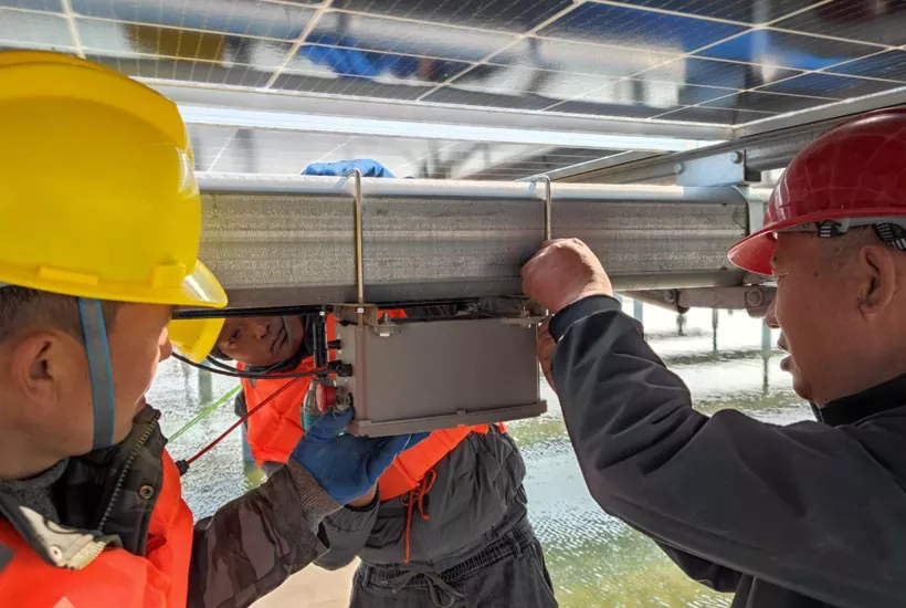
Phase 4: Environment and Interference Assessment (Prevention, Detection, Measurement)
Electromagnetic Interference Check: Ensure that communication cable shielding is properly grounded and that communication cables are not routed alongside high-voltage power lines. For RS485 communication, confirm that the A/B wires are connected correctly and that 120 Ω termination resistors are installed at both ends of the bus.
Environmental Protection Check: Check whether the enclosure sealing strips are aged to prevent condensation from causing minor short circuits on the circuit board. Confirm that the operating temperature remains within the industrial-grade range to avoid shutdowns caused by high or low temperatures.
Phase 5: Upgrade Handling and Recording
Manufacturer Support: If the issue remains unresolved after the first four phases, record all fault details, including indicator status, error codes, and test messages. Contact the manufacturer's technical support team for chip-level inspection and repair.
Work Order Documentation: Complete the NCU Troubleshooting Record Form with the inspection steps, replacement part model, and final resolution. Upload the record to the intelligent O&M platform for filing.
Common Faults and Solutions
Issue 1: NCU cannot connect to SCADA
Causes: Network anomaly, incorrect IP configuration, protocol mismatch, communication module failure.
Inspection methods: Check network ports, fiber optics, and network status; verify network parameters; check protocol settings (e.g., Modbus); inspect hardware status.
Issue 2: Some TCUs are offline
Possible causes: RS485 line fault, address conflict, excessive communication distance, incorrect terminal resistor configuration.
Corrective actions: Check communication lines, verify device addresses, and test communication quality.
Issue 3: NCU frequently reboots
Possible causes: Unstable power supply, excessive temperature, software anomaly.
Recommendations: Check the power supply voltage, review operation logs, and contact the manufacturer's technical support.
Smarter Operation and Maintenance Support
Suzhou Ruitai's NCU uses built-in intelligent diagnostics and standardized troubleshooting procedures to reduce fault diagnosis from days to minutes.
Combined with remote O&M software, it allows O&M personnel to complete remote commissioning and firmware upgrades without frequent site visits, reducing manual O&M costs and supporting safe, efficient solar power plant operation.
Hot Tags: photovoltaic communication unit supplier, PV communication unit manufacturer, solar communication system factory
Send Inquiry
Contact Info
-
Address
Building 10, Jiangsu Hainde High tech Industrial Park, No. 70 Yaofeng West Road, Mudu Town, Wuzhong District, Suzhou City, Jiangsu Province, China
-
Tel
-
E-mail
Send Us Your Project Details
Get a Tailored Quote Within 24 Hours
- ● Factory-Direct Pricing: No middlemen—you get competitive costs straight from our Suzhou plant.
- ● Fast Response: Our technical team replies within 24 hours with initial recommendations.
- ● Custom Solutions: We tailor TCU strategies, communication setups, and SCADA dashboards to your needs.
- ● Global Support: From commissioning to after-sales, our engineers are ready to assist worldwide.